The OSI (Open System Interconnection) Model explains how data is packaged and sent, how devices handle errors and how application services talk to underlying network protocols. It breaks down network communication into layers. Each layer handles tasks that support the overall data exchange. This layered approach makes sense. It separates lower level physical transmissions from higher level application processes. It allows different protocols, devices and software to work together.
In this article we will define it, explain its features, go through each of the 7 layers, show how data flows and then compare it to the more widely used TCP/IP model. Along the way we will also point out the advantages and disadvantages.
Let’s begin:
What Is the OSI Model?
(Credits)
The Open System Interconnection model is a reference framework for network communication. It organizes tasks into seven layers, each dedicated to specific operations. It is conceptual, not tied to a single technology or vendor. OSI model shapes how engineers, architects, and t500_prod_administrators analyze network traffic and troubleshoot issues. It promotes better design and clearer logic by structuring communication steps.
Here are the seven layers of the OSI model:
- Physical Layer
- Data Link Layer
- Network Layer
- Transport Layer
- Session Layer
- Presentation Layer
- Application Layer
Characteristics of OSI Model
Let us understand the guiding principles that shaped its design. These principles demonstrate why the model is still relevant, even decades after its formalization:
- Layered Structure
The model divides data handling into seven layers. Each layer passes data to the next in a strict hierarchy. This structure aids in diagnosing errors. Failures can be pinpointed to a certain layer.
- Separation of Concerns
Layers isolate tasks. Hardware tasks, such as signal transmission, remain in the lower layers. Software-intensive tasks, such as data encoding, reside in the upper layers.
- Standardized Interfaces
Adjacent layers share defined interfaces. These interfaces specify how information moves from one layer to the next. Vendors can develop products that fit into a specific layer without breaking compatibility.
- Independence Within Layers
Each layer focuses on a certain responsibility. This separation allows new protocols to replace old ones. Changes at one layer do not force changes at another, if the interfaces remain intact.
- Universality
The OSI Model is vendor-neutral. It accommodates numerous protocols and technologies. Ethernet, Wi-Fi, IP, and others can fit into this model.
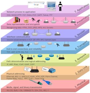
7 Layers of OSI Model
Below is an in-depth look at each of the OSI layers. We will briefly introduce the layer’s primary focus, then expand on how it fits into the broader flow of data across a network.
1. Physical Layer
This is the lowest layer. It deals with raw bit transmission over a physical medium. Bits become electrical signals, optical pulses, or radio waves. Typical components include cables, connectors, transceivers, and wireless standards. This layer sets the fundamental interface between the system and the medium.
Functions of Physical Layer
- Converts digital bits into signals.
- Sets electrical or optical specifications.
- Regulates data rates (bits per second).
- Defines voltage levels, modulation schemes, and physical connectors.
2. Data Link Layer
This layer ensures point-to-point data transfer between nodes connected on the same network segment. It structures raw bits into frames. It addresses frames with physical (MAC) addresses. It checks for errors introduced by the Physical Layer.
Functions of Data Link Layer
- Groups bits into frames.
- Uses Media Access Control (MAC) addresses.
- Manages collisions and shared-medium access (CSMA/CD, for instance).
- Implements error detection and, in some cases, basic error correction.
- Handles flow control to avoid overwhelming slower devices.
3. Network Layer
This layer deals with sending packets from source to destination across potentially multiple networks. It selects routing paths and addresses packets with logical addresses, such as IP addresses. Routers operate here, deciding where a packet goes next.
Functions of Network Layer
- Assigns source and destination IP addresses.
- Determines best routes (routing protocols, such as OSPF or BGP).
- Manages fragmentation if a packet exceeds network limits.
- Handles congestion control at a network scope.
4. Transport Layer
This layer segments data from the upper layers, then ensures reliable or fast delivery. It assigns port numbers, controlling how data is funneled to applications. It also handles flow control and error recovery. Two common protocols in this layer are TCP (reliable, connection-based) and UDP (faster, connectionless).
Functions of Transport Layer
- Breaks data into segments and reassembles them on the receiving side.
- Uses port numbers to map traffic to applications or services.
- Provides reliability (TCP) or speed (UDP).
- Manages end-to-end flow control.
- Retransmits lost segments when reliability is needed.
5. Session Layer
This layer sets up, controls, and closes dialogues between devices. It tracks sessions, enabling them to resume if interruptions happen. Many modern technologies merge Session Layer tasks with other layers, but session control remains essential in distributed systems.
Functions of Session Layer
- Initiates and terminates sessions between endpoints.
- Maintains separate sessions for different tasks.
- Synchronizes with checkpoints to reduce retransmission after interruptions.
- Handles authentication and authorization in some cases.
6. Presentation Layer
This layer is about data representation. It translates, compresses and encrypts. It ensures the data structured on the sender side is interpretable by the receiver. For example, text encoding from ASCII to EBCDIC or encryption and decryption processes occur here. Compression to save bandwidth also belongs to this layer.
Functions of Presentation Layer
- Translates data formats (e.g., character sets, images, sound).
- Encrypts data to protect confidentiality.
- Compresses files to reduce size.
- Decompresses and decrypts on the receiving end.
7. Application Layer
This layer is closest to the user. It has protocols for file sharing, emailing, web browsing and other user facing tasks. Examples are HTTP, SMTP and FTP. It provides an interface for software applications to request network services.
Functions of Application Layer
- Interprets requests from user applications (web browsers, email clients).
- Coordinates remote file access or message handling.
- Implements high-level protocols for communications and resource sharing.
- Bridges user processes and the underlying OSI stack.
How Data Flows in the OSI Model?
The OSI Model handles data in a top-down and bottom-up manner. At the sender’s end, the data starts at the Application Layer and proceeds downward:
- Application Layer
Data is generated by a client application.
- Presentation Layer
Data is possibly encrypted or compressed. The format is standardized if different systems have different data formats.
- Session Layer
A session is initiated, tracked, and managed.
- Transport Layer
Data is segmented. A transport protocol (TCP or UDP) is chosen. Port numbers define the targeted service. Reliability features (acknowledgments, checksums) may be added.
- Network Layer
Segments are enclosed in packets. IP addresses are placed in the header. Routing decisions are prepared.
- Data Link Layer
Packets are put into frames. Physical addresses (MAC) are assigned. Link-level error checks are added.
- Physical Layer
Frames become signals on a cable, fiber, or wireless channel.
On the receiver side, the reverse occurs. The Physical Layer collects the signal and converts it back to frames. Each subsequent layer strips headers, interprets data, and delivers it up the stack. The final stage is at the Application Layer, where the data is presented to user software. At each layer, the headers (and trailers, for data link) contain unique control information that steers the flow and ensures correct addressing and handling.
Thus, data flow in the Open System Interconnection model typically unfolds from top to bottom on the sending side and from bottom to top on the receiving side. Here is a quick illustration:
Application (Layer 7) → Presentation (6) → Session (5): The user’s application creates data. It may be encrypted or compressed, and a session is opened to coordinate the exchange.
Transport (4): The data is segmented and assigned port numbers. If TCP is used, a reliable connection is established; if UDP, data is simply sent without formal setup.
Network (3): Packets receive source and destination IP addresses. Routers along the path use these to forward the packets.
Data Link (2): Frames are created and marked with MAC addresses. Local network devices ensure frames get to the next hop.
Physical (1): Frames are converted to electrical signals, light pulses, or radio waves for actual transmission across the wire or through the air.
Upon arrival at the destination, each layer strips its corresponding header (or trailer) and interprets the data. The reassembled data is then passed to the receiving application at Layer 7. This layered approach makes it easy to troubleshoot. If packets are not reaching the destination, check the Physical Layer or Data Link Layer first. If the packets arrive but the application sees garbled text, the Presentation Layer might be misconfigured.
Protocols Used in the OSI Layers
Although the OSI Model is conceptual, real-world protocols map well to its layers. Below is a quick reference table:
|
OSI Layer |
Protocol Examples |
Data Unit |
|
Physical (Layer 1) |
IEEE 802.3 (Ethernet physical), SONET, DSL, Wi-Fi radios |
Bits |
|
Data Link (Layer 2) |
Ethernet MAC, PPP, HDLC |
Frames |
|
Network (Layer 3) |
IP, ICMP, ARP, OSPF, BGP |
Packets |
|
Transport (Layer 4) |
TCP, UDP, SCTP |
Segments |
|
Session (Layer 5) |
RPC, NetBIOS sessions, PPTP |
Data (Session) |
|
Presentation (L6) |
SSL/TLS, MIME, JPEG, ASCII/EBCDIC conversion |
Data (Presentation) |
|
Application (L7) |
HTTP, SMTP, FTP, DNS, SNMP |
Data (Application) |
Some layers handle multiple protocols. The choice depends on the requirements. For example, multimedia uses UDP for low latency, while file transfers rely on TCP.
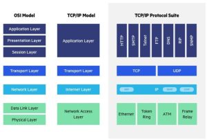
Difference Between OSI and TCP/IP Model
(Credits)
Although the OSI Model is a good teaching and reference tool, most modern networks, especially the internet, uses the TCP/IP suite of protocols. The TCP/IP model has four main layers:
- Application Layer (TCP/IP)
Maps to OSI Layers 5, 6, and 7 (Session, Presentation, and Application).
- Transport Layer (TCP/IP)
Matches OSI Layer 4 (Transport).
- Internet Layer (TCP/IP)
Corresponds to OSI Layer 3 (Network).
- Network Access Layer (TCP/IP)
Combines OSI Layers 1 and 2 (Physical, Data Link).
Here’s the difference between OSI and TCP/IP model in a tabulated format:
|
Aspect |
OSI Model |
TCP/IP Model |
|
Layers |
7 |
4 |
|
Origin |
Designed by ISO in late 1970s/early 1980s |
Developed by DARPA (for ARPANET, which became the Internet) |
|
Structure |
Strict separation of each layer |
More flexible boundaries |
|
Usage |
Primarily a reference model |
Practically deployed for internet traffic |
|
Integration |
Presentation and Session are distinct |
Both combined with Application |
|
Transport |
Connection-oriented or connectionless (layer 4) |
TCP or UDP (Transport layer) |
|
Focus |
Comprehensive theoretical outline |
Implementation and real-world protocols |
OSI’s layered framework suits conceptual teaching and troubleshooting. TCP/IP is used in all modern networks. In practice, the industry references both models for different needs.
Advantages of OSI Model
Before we get into the disadvantages, let us first note the benefits that the OSI Model brings to networking theory and practice:
- Clear Segmentation of Tasks
Each layer does one thing. This delineation makes it simpler to develop, test, or replace components without disturbing the entire stack.
- Modular Approach
Designers can focus on one layer’s functionality. Hardware makers target physical and data link responsibilities, while software groups develop transport or application protocols.
- Diagnostic Benefits
Problems become easier to locate. If a node sees a frame error, the Data Link Layer is investigated. If an IP routing loop occurs, the Network Layer is examined.
- Scalability
Systems can add new protocols or replace old ones. As long as the interface between layers remains unchanged, the rest of the architecture continues functioning smoothly.
- Universal Reference
Vendors, academics, and engineers share a common standard. This fosters improved communication and collaboration.
Disadvantages of OSI Model
While the OSI Model is indispensable for conceptual clarity, it does not come without a few limitations. Below is a concise overview that shows why some criticisms persist in modern usage.
- Theoretical Emphasis
The OSI Model was introduced after TCP/IP was already in use. As a result, network deployments favored TCP/IP directly. Some details in OSI do not always map neatly to real systems.
- Redundancy in Layers
Certain OSI layers (Session and Presentation) are frequently integrated into other layers in live networks. This can create confusion about how software stacks align with OSI.
- Complex Implementation
Full OSI compliance is rare. Vendors often pick subsets or reinterpret certain layers, which can make multi-vendor environments complex.
- Not Always Relevant to Modern Use Cases
Virtualization, cloud and overlay networks might group OSI responsibilities differently. The model still applies but these innovations sometimes hide layers behind software defined solutions.
Conclusion
At its simplest the Open System Interconnection model explains “who does what” in network communications: the cables and signals in the Physical Layer, the frames and MAC addressing in the Data Link Layer, the routing logic in the Network Layer, all the way up to the user oriented protocols in the Application Layer. But it is more than just a hierarchical list. It is a lens that can reveal which parts of a network might be failing when communication breaks down, and it provides a lingua franca for teams discussing network design, hardware selection, and protocol adoption.
Even though TCP/IP is what’s used in production, the OSI model still matters. It gives us a way to think about and talk about networking tasks, especially in big or complex environments.
Looking for a high TC job? Stop searching and start applying on Talent500 now!